目录
前言
在学习OSPF路由协议的时候,刚好学校课程老师在讲解OSPF路由协议,所以听了个大概后,布置了个实验,其实也就是实现课本上的实验拓扑图,但是这个实验又不完全是OSPF路由协议,还有关于一些多生成树MSTP、虚拟路由冗余协议VRRP等等配置。(我是到处都学一点,像STP一些杂乱的东西,所以在这里重新总结一下)
项目背景
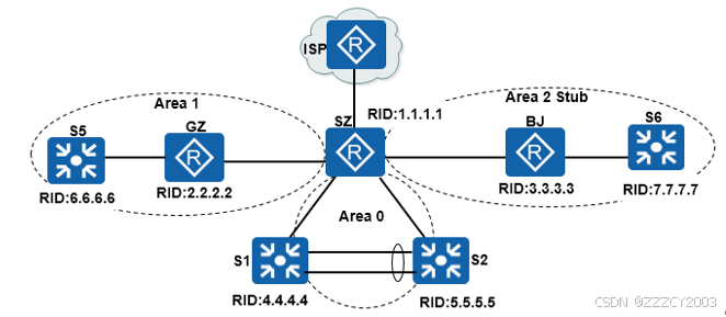
为了确保资源共享、办公自动化和节省人力成本,公司E申请两条专线将深圳总部和广州、北京两家分公司网络连接起来。张同学正在该公司实习,为了提高实际工作的准确性和工作效率,项目经理安排他在实验室环境下完成测试,为设备上线运行奠定坚实的基础。小张用1台路由器模拟ISP的网络,总部通过静态默认路由实现到ISP的连接。分公司和总部内部网络通过三层交换机实现VLAN间路由,总部和分公司运行OSPF路由协议实现网络互联。
实验拓扑
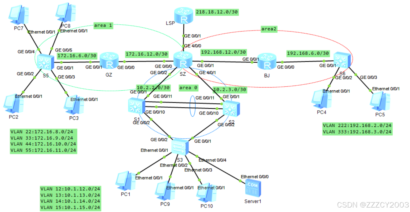
项目目标
前期准备
- **VLAN部署:**在总部和分公司相应交换机上完成VLAN相关配置,包括VLAN创建和端口划分、Trunk配置等。在交换机S1和S2之间链路配置链路聚合
- **MSTP部署:**在交换机S1、S2和S3上配置MSTP,通过实例1(VLAN12和VLAN13)和实例2(VLAN14和VLAN15)选举不同的根桥实现负载分担。交换机S1是实例1的根桥(优先级为4096),是实例2的次根桥(优先级为8192);交换机S2是实例1的次根桥(优先级为8192),是实例2的根桥(优先级为4096)
- **IP地址部署:**在总部和分公司设备上完成IP地址配置,包括配置路由器接口的IP地址、三层交换机创建VLANIF并配置IP地址以及配置计算机和服务器的IP地址、子网掩码和网关
- **VRRP部署:**总部核心交换机S1和S2配置VRRP,为各个VLAN主机提供冗余网关。通过配置使得交换机S1作为VLAN12和VLAN13的Master,交换机S2作为VLAN14和VLAN15的Master。确保每个VLAN的VRRP的Master和MSTP的根一致
- **NAT部署:**配置NAT,使得总部和分公司的主机可以通过路由器SZ访问Internet
项目核心(OSPF)
- **配置OSPF基本功能:**创建OSPF进程,手动指定Router ID、修改OSPF计算度量值参考带宽为1000Mbit/s、激活运行OSPF的路由器接口等。广州和深圳网络划分到OSPF区域1,深圳和北京网络划分到OSPF区域2,深圳总部网络划分到OSPF区域0。为了减少向局域网发送不必要的OSPF更新,将分公司交换机适当接口配置为静默接口
- **配置Stub区域:**将区域2配置为完全末节区域
- **配置OSPF验证:**为了提高网络安全性,在深圳总部到分公司的两条链路上,配置OSPF MD5验证。在深圳总部的OSPF区域0设备上配置MD5验证
- **配置OSPF路由聚合:**在路由器SZ上分别配置OSPF区域0、1和2的ABR路由聚合,以便减少路由表大小,提高路由查找效率
- **配置OSPF默认路由注入:**在路由器SZ上配置指向ISP的静态默认路由,并向OSPF网络注入默认路由
- **控制OSPF DR选举:**控制DR选举,使得路由器SZ成为连接三层交换机S1和S2的相应网段的DR
- **调整OSPF计时器:**在深圳和北京连接的链路上,将接口发送Hello报文间隔改为5秒,Dead时间改为20秒
| 设备 | VLAN ID | IP地址段 | VLAN接口地址 |
|---|---|---|---|
| S1 | VLAN 2 | 10.2.2.0/30 | 10.2.2.2/30 |
| VLAN 12 | 10.1.12.0/24 | 10.1.12.252/24 | |
| VLAN 13 | 10.1.13.0/24 | 10.1.13.252/24 | |
| VLAN 14 | 10.1.14.0/24 | 10.1.14.252/24 | |
| VLAN 15 | 10.1.15.0/24 | 10.1.15.252/24 | |
| S2 | VLAN 3 | 10.2.3.0/30 | 10.2.3.2/30 |
| VLAN 12 | 10.1.12.0/24 | 10.1.12.253/24 | |
| VLAN 13 | 10.1.13.0/24 | 10.1.13.253/24 | |
| VLAN 14 | 10.1.14.0/24 | 10.1.14.253/24 | |
| VLAN 15 | 10.1.15.0/24 | 10.1.15.253/24 | |
| S3 | VLAN 12 | 10.1.12.0/24 | 10.1.12.254/24 |
| VLAN 13 | 10.1.13.0/24 | 10.1.13.254/24 | |
| VLAN 14 | 10.1.14.0/24 | 10.1.14.254/24 | |
| VLAN 15 | 10.1.15.0/24 | 10.1.15.254/24 | |
| S5 | VLAN 22 | 172.16.8.0/24 | 172.16.8.254/24 |
| VLAN 33 | 172.16.9.0/24 | 172.16.9.254/24 | |
| VLAN 44 | 172.16.10.0/24 | 172.16.10.254/24 | |
| VLAN 55 | 172.16.11.0/24 | 172.16.11.254/24 | |
| VLAN 66 | 172.16.6.0/30 | 172.16.6.2/30 | |
| S6 | VLAN 223 | 192.168.2.0/24 | 192.168.2.254/24 |
| VLAN 333 | 192.168.3.0/24 | 192.168.3.254/24 | |
| VLAN 666 | 192.168.6.0/30 | 192.168.6.2/30 |
| 设备 | 接口 | 接口类型 | VLAN | 链路聚合 | 对端设备及接口 |
|---|---|---|---|---|---|
| S1 | G0/0/1 | Access | VLAN 2 | SZ G0/0/2 | |
| G0/0/2 | Trunk | S3 G0/0/2 | |||
| G0/0/10 | Trunk | 是 | S2 G0/0/10 | ||
| G0/0/11 | Trunk | 是 | S2 G0/0/11 | ||
| S2 | G0/0/1 | Access | VLAN 3 | SZ G0/0/2 | |
| G0/0/2 | Trunk | S3 G0/0/2 | |||
| G0/0/10 | Trunk | 是 | S2 G0/0/10 | ||
| G0/0/11 | Trunk | 是 | S2 G0/0/11 | ||
| S3 | Ethernet0/0/1 | Access | VLAN 12 | PC1 | |
| Ethernet0/0/2 | Access | VLAN 13 | PC9 | ||
| Ethernet0/0/3 | Access | VLAN 14 | PC10 | ||
| Ethernet0/0/4 | Access | VLAN 15 | Server1 | ||
| G0/0/1 | Trunk | S2 G0/0/2 | |||
| G0/0/2 | Trunk | S1 G0/0/2 | |||
| S5 | G0/0/1 | Access | VLAN 66 | GZ G0/0/1 | |
| G0/0/2 | Access | VLAN 22 | PC2 | ||
| G0/0/3 | Access | VLAN 33 | PC3 | ||
| G0/0/4 | Access | VLAN 44 | PC7 | ||
| G0/0/5 | Access | VLAN 55 | PC8 | ||
| S6 | G0/0/1 | Access | VLAN 666 | BJ G0/0/0 | |
| G0/0/2 | Access | VLAN 222 | PC4 | ||
| G0/0/3 | Access | VLAN 333 | PC5 | ||
| SZ | G0/0/0 | GZ G0/0/0 | |||
| G0/0/1 | BJ G0/0/1 | ||||
| G0/0/2 | S1 G0/0/1 | ||||
| G4/0/1 | S2 G0/0/1 | ||||
| G4/0/0 | LSP G0/0/1 | ||||
| GZ | G0/0/0 | SZ G0/0/0 | |||
| G0/0/1 | S5 G0/0/1 | ||||
| BJ | G0/0/0 | S6 G0/0/0 | |||
| G0/0/1 | SZ G0/0/1 | ||||
| LSP | G0/0/0 | SZ G4/0/0 | |||
| LoopBack0 |
| 设备 | 接口 | IP地址 | 备注 |
|---|---|---|---|
| SZ | G0/0/0 | 172.16.12.2/30 | |
| G0/0/1 | 192.168.12.1/30 | ||
| G0/0/2 | 10.2.2.1/30 | ||
| G4/0/1 | 10.2.3.1/30 | ||
| G4/0/0 | 218.18.12.1/30 | ||
| GZ | G0/0/0 | 172.16.12.1/30 | |
| G0/0/1 | 172.16.6.2/30 | ||
| BJ | G0/0/0 | 192.168.6.1/30 | |
| G0/0/1 | 192.168.12.2/30 | ||
| LSP | G0/0/1 | 218.18.12.2/30 | |
| LoopBack0 | 8.8.8.8/24 | 模拟Internet上主机 | |
| PC1 | 10.1.12.100/24 | 网关:10.1.12.254 | |
| PC2 | 172.16.8.100/24 | 网关:172.16.8.254 | |
| PC3 | 172.16.9.100/24 | 网关:172.16.9.254 | |
| PC4 | 192.168.2.100/24 | 网关:192.168.2.254 | |
| PC5 | 192.168.3.100/24 | 网关:192.168.3.254 | |
| PC7 | 172.16.10.100/24 | 网关:172.16.10.254 | |
| PC8 | 172.16.11.100/24 | 网关:172.16.11.254 | |
| PC9 | 10.1.13.100/24 | 网关:10.1.13.254 | |
| PC10 | 10.1.14.100/24 | 网关:10.1.14.254 | |
| Server1 | 10.1.15.100/24 | 网关:10.1.15.254 |
别问为什么PC机的序号是乱的,因为我是乱放的。。。
项目步骤
准备工作
(1)配置VLAN
在总部和分公司相应交换机上完成VLAN相关配置,包括VLAN创建和端口划分、Trunk配置。在交换机S1和S2之间链路配置链路聚合
S1配置
展开代码[S1]vlan batch 2 12 to 15
[S1]interface Eth-Trunk1
[S1-Eth-Trunk1]port link-type trunk
[S1-Eth-Trunk1]port trunk allow-pass vlan 2 to 4094
# 设置负载均衡策略为源MAC和目的MAC
[S1-Eth-Trunk1]load-balance src-dst-mac
[S1-Eth-Trunk1]quit

[S1]interface GigabitEthernet0/0/1
[S1-GigabitEthernet0/0/1]port link-type access
[S1-GigabitEthernet0/0/1]port default vlan 2
[S1-GigabitEthernet0/0/1]quit

[S1]interface GigabitEthernet0/0/2
[S1-GigabitEthernet0/0/2]port link-type trunk
[S1-GigabitEthernet0/0/2]port trunk allow-pass vlan 2 to 4094
[S1-GigabitEthernet0/0/2]quit

# 将G0/0/10和G0/0/11接口加入链路聚合组1
[S1]interface GigabitEthernet0/0/10
[S1-GigabitEthernet0/0/10]eth-trunk 1
[S1-GigabitEthernet0/0/10]quit

[S1]interface GigabitEthernet0/0/11
[S1-GigabitEthernet0/0/11]eth-trunk 1
[S1-GigabitEthernet0/0/11]quit
S2配置
展开代码[S2]vlan batch 2 to 3 12 to 15
[S2]interface Eth-Trunk1
[S2-Eth-Trunk1]port link-type trunk
[S2-Eth-Trunk1]port trunk allow-pass vlan 2 to 4094
[S2-Eth-Trunk1]load-balance src-dst-mac
[S2-Eth-Trunk1]quit

[S2]interface GigabitEthernet0/0/1
[S2-GigabitEthernet0/0/1]port link-type access
[S2-GigabitEthernet0/0/1]port default vlan 3
[S2-GigabitEthernet0/0/1]quit

[S2]interface GigabitEthernet0/0/2
[S2-GigabitEthernet0/0/2]port link-type trunk
[S2-GigabitEthernet0/0/2]port trunk allow-pass vlan 2 to 4094
[S2-GigabitEthernet0/0/2]quit

# 将G0/0/10和G0/0/11加入链路聚合组1
[S2]interface GigabitEthernet0/0/10
[S2-GigabitEthernet0/0/10]eth-trunk 1
[S2-GigabitEthernet0/0/10]quit

[S2]interface GigabitEthernet0/0/11
[S2-GigabitEthernet0/0/11]eth-trunk 1
[S2-GigabitEthernet0/0/11]quit
S3配置
其实这里的S3交换机就是二层(傻瓜)交换机
展开代码[S3]vlan batch 12 to 15
[S3]interface Ethernet0/0/1
[S3-Ethernet0/0/1]port link-type access
[S3-Ethernet0/0/1]port default vlan 12
[S3-Ethernet0/0/1]quit

[S3]interface Ethernet0/0/2
[S3-Ethernet0/0/2]port link-type access
[S3-Ethernet0/0/2]port default vlan 13
[S3-Ethernet0/0/2]quit

[S3]interface Ethernet0/0/3
[S3-Ethernet0/0/3]port link-type access
[S3-Ethernet0/0/3]port default vlan 14
[S3-Ethernet0/0/3]quit

[S3]interface Ethernet0/0/4
[S3-Ethernet0/0/4]port link-type access
[S3-Ethernet0/0/4]port default vlan 15
[S3-Ethernet0/0/4]quit

[S3]interface GigabitEthernet0/0/1
[S3-GigabitEthernet0/0/1]port link-type trunk
[S3-GigabitEthernet0/0/1]port trunk allow-pass vlan 2 to 4094
[S3-GigabitEthernet0/0/1]quit
[S3]interface GigabitEthernet0/0/2
[S3-GigabitEthernet0/0/2]port link-type trunk
[S3-GigabitEthernet0/0/2]port trunk allow-pass vlan 2 to 4094
[S3-GigabitEthernet0/0/2]quit
S5配置
展开代码[S5]vlan batch 22 33 44 55 66
[S5]interface GigabitEthernet0/0/1
[S5-GigabitEthernet0/0/1]port link-type access
[S5-GigabitEthernet0/0/1]port default vlan 66
[S5-GigabitEthernet0/0/1]quit

[S5]interface GigabitEthernet0/0/2
[S5-GigabitEthernet0/0/2]port link-type access
[S5-GigabitEthernet0/0/2]port default vlan 22
[S5-GigabitEthernet0/0/2]quit

[S5]interface GigabitEthernet0/0/3
[S5-GigabitEthernet0/0/3]port link-type access
[S5-GigabitEthernet0/0/3]port default vlan 33
[S5-GigabitEthernet0/0/3]quit

[S5]interface GigabitEthernet0/0/4
[S5-GigabitEthernet0/0/4]port link-type access
[S5-GigabitEthernet0/0/4]port default vlan 44
[S5-GigabitEthernet0/0/4]quit

[S5]interface GigabitEthernet0/0/5
[S5-GigabitEthernet0/0/5]port link-type access
[S5-GigabitEthernet0/0/5]port default vlan 55
[S5-GigabitEthernet0/0/5]quit
S6配置
展开代码[S6]vlan batch 222 333 666
[S6]interface GigabitEthernet0/0/1
[S6-GigabitEthernet0/0/1]port link-type access
[S6-GigabitEthernet0/0/1]port default vlan 666
[S6-GigabitEthernet0/0/1]quit

[S6]interface GigabitEthernet0/0/2
[S6-GigabitEthernet0/0/2]port link-type access
[S6-GigabitEthernet0/0/2]port default vlan 222
[S6-GigabitEthernet0/0/2]quit

[S6]interface GigabitEthernet0/0/3
[S6-GigabitEthernet0/0/3]port link-type access
[S6-GigabitEthernet0/0/3]port default vlan 333
[S6-GigabitEthernet0/0/3]quit
验证
可以用以下三个命令验证是否配置好
展开代码# 验证VLAN配置
[S1]display vlan

# 验证Eth-Trunk配置
[S1]display eth-trunk 1

# 验证Trunk配置
[S1]display port vlan
(2)配置MSTP
在交换机S1、S2和S3上配置MSTP,通过实例1(VLAN12和VLAN13)和实例2(VLAN14和VLAN15)选举不同的根桥实现负载分担。交换机S1是实例1的根桥(优先级为4096),是实例2的次根桥(优先级为8192);交换机S2是实例1的次根桥(优先级为8192),是实例2的根桥(优先级为4096)
S1配置
展开代码# 配置实例优先级
[S1]stp instance 1 priority 4096
[S1]stp instance 2 priority 8192
# 进入STP区域配置模式
[S1]stp region-configuration

# 设置MSTP区域名称为HQ
[S1-mst-region]region-name HQ

# 将VLAN 12和13分配到实例1
[S1-mst-region]instance 1 vlan 12 to 13

# 将VLAN 14和15分配到实例2
[S1-mst-region]instance 2 vlan 14 to 15

# 激活MSTP区域配置
[S1-mst-region]active region-configuration
[S1-mst-region]quit
S2配置
展开代码# 配置实例优先级
[S2]stp instance 1 priority 8192
[S2]stp instance 2 priority 4096

# 进入STP区域配置模式
[S2]stp region-configuration

# 设置MSTP区域名称为HQ
[S2-mst-region]region-name HQ

# 将VLAN 12和13分配到实例1
[S2-mst-region]instance 1 vlan 12 to 13

# 将VLAN 14和15分配到实例2
[S2-mst-region]instance 2 vlan 14 to 15

# 激活MSTP区域配置
[S2-mst-region]active region-configuration
[S2-mst-region]quit
S3配置
展开代码[S3]stp region-configuration
[S3-mst-region]region-name HQ
[S3-mst-region]instance 1 vlan 12 to 13
[S3-mst-region]instance 2 vlan 14 to 15
[S3-mst-region]active region-configuration
[S3-mst-region]
验证
展开代码[S1]display stp brief
 MSTID  Port                    Role   STP State           Protection
   0    GigabitEthernet0/0/1        DESI  FORWARDING      NONE
   0    GigabitEthernet0/0/2        DESI  FORWARDING      NONE
   0    Eth-Trunk1                ROOT  FORWARDING     NONE
   1    GigabitEthernet0/0/2        DESI  FORWARDING      NONE
   1    Eth-Trunk1               DESI  FORWARDING       NONE
   2    GigabitEthernet0/0/2        DESI  FORWARDING      NONE
   2    Eth-Trunk1               ROOT  FORWARDING      NONE
(3)配置IP地址
在总部和分公司设备上完成IP地址配置,包括配置路由器接口的IP地址、三层交换机创建VLANIF并配置IP地址以及配置计算机和服务器的IP地址、子网掩码和网关
SZ配置
展开代码[SZ]interface GigabitEthernet0/0/0
[SZ-GigabitEthernet0/0/0]ip address 172.16.12.2 255.255.255.252
[SZ-GigabitEthernet0/0/0]quit

[SZ]interface GigabitEthernet0/0/1
[SZ-GigabitEthernet0/0/1]ip address 192.168.12.1 255.255.255.252
[SZ-GigabitEthernet0/0/1]quit

[SZ]interface GigabitEthernet0/0/2
[SZ-GigabitEthernet0/0/2]ip address 10.2.2.1 255.255.255.252
[SZ-GigabitEthernet0/0/2]quit

[SZ]interface GigabitEthernet4/0/1
[SZ-GigabitEthernet1/0/0]ip address 10.2.3.1 255.255.255.252
[SZ-GigabitEthernet1/0/0]quit

[SZ]interface GigabitEthernet4/0/0
[SZ-GigabitEthernet2/0/0]ip address 218.18.12.1 255.255.255.252
[SZ-GigabitEthernet2/0/0]quit
GZ配置
展开代码[GZ]interface GigabitEthernet0/0/0
[GZ-GigabitEthernet0/0/0]ip address 172.16.12.1 255.255.255.252
[GZ-GigabitEthernet0/0/0]quit

[GZ]interface GigabitEthernet0/0/1
[GZ-GigabitEthernet0/0/1]ip address 172.16.6.2 255.255.255.252
[GZ-GigabitEthernet0/0/1]quit
BJ配置
展开代码[BJ]interface GigabitEthernet0/0/0
[BJ-GigabitEthernet0/0/0]ip address 192.168.6.1 255.255.255.252
[BJ-GigabitEthernet0/0/0]quit

[BJ]interface GigabitEthernet0/0/1
[BJ-GigabitEthernet0/0/1]ip address 192.168.12.2 255.255.255.252
[BJ-GigabitEthernet0/0/1]quit
LSP配置
展开代码[ISP]interface GigabitEthernet0/0/0
[ISP-GigabitEthernet0/0/0]ip address 218.18.12.2 255.255.255.252
[ISP-GigabitEthernet0/0/0]quit

# 配置环回地址
[ISP]interface LoopBack0
[ISP-LoopBack0]ip address 8.8.8.8 255.255.255.0
[ISP-LoopBack0]quit
S1配置
展开代码[S1]interface Vlanif2
[S1-Vlanif2]ip address 10.2.2.2 255.255.255.252
[S1-Vlanif2]quit

[S1]interface Vlanif12
[S1-Vlanif12]ip address 10.1.12.252 255.255.255.0
[S1-Vlanif12]quit

[S1]interface Vlanif13
[S1-Vlanif13]ip address 10.1.13.252 255.255.255.0
[S1-Vlanif13]quit

[S1]interface Vlanif14
[S1-Vlanif14]ip address 10.1.14.252 255.255.255.0
[S1-Vlanif14]quit

[S1]interface Vlanif15
[S1-Vlanif15]ip address 10.1.15.252 255.255.255.0
[S1-Vlanif15]quit
S2配置
展开代码[S2]interface Vlanif3
[S2-Vlanif3]ip address 10.2.3.2 255.255.255.252
[S2-Vlanif3]quit

[S2]interface Vlanif12
[S2-Vlanif12]ip address 10.1.12.253 255.255.255.0
[S2-Vlanif12]quit

[S2]interface Vlanif13
[S2-Vlanif13]ip address 10.1.13.253 255.255.255.0
[S2-Vlanif13]quit

[S2]interface Vlanif14
[S2-Vlanif14]ip address 10.1.14.253 255.255.255.0
[S2-Vlanif14]quit

[S2]interface Vlanif15
[S2-Vlanif15]ip address 10.1.15.253 255.255.255.0
[S2-Vlanif15]quit
S5配置
展开代码[S5]interface Vlanif22
[S5-Vlanif2]ip address 172.16.8.254 255.255.255.0
[S5-Vlanif2]quit

[S5]interface Vlanif33
[S5-Vlanif3]ip address 172.16.9.254 255.255.255.0
[S5-Vlanif3]quit

[S5]interface Vlanif44
[S5-Vlanif4]ip address 172.16.10.254 255.255.255.0
[S5-Vlanif4]quit

[S5]interface Vlanif55
[S5-Vlanif5]ip address 172.16.11.254 255.255.255.0
[S5-Vlanif5]quit

[S5]interface Vlanif66
[S5-Vlanif6]ip address 172.16.6.1 255.255.255.252
[S5-Vlanif6]quit
S6配置
展开代码[S6]interface Vlanif222
[S6-Vlanif2]ip address 192.168.2.254 255.255.255.0
[S6-Vlanif2]quit

[S6]interface Vlanif333
[S6-Vlanif3]ip address 192.168.3.254 255.255.255.0
[S6-Vlanif3]quit

[S6]interface Vlanif666
[S6-Vlanif6]ip address 192.168.6.2 255.255.255.252
[S6-Vlanif6]quit
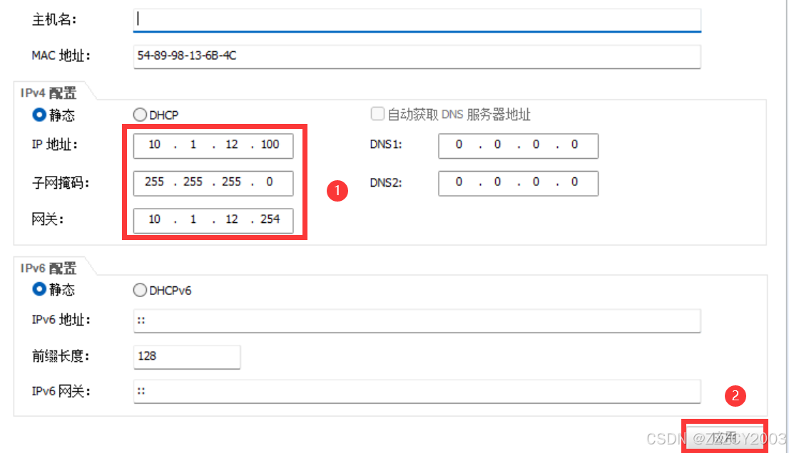
以PC1为例,配置IP地址、掩码、网关
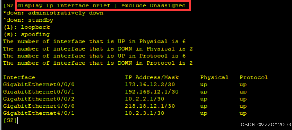
验证
(4)配置VRRP
总部核心交换机S1和S2配置VRRP,为各个VLAN主机提供冗余网关。通过配置使得交换机S1作为VLAN12和VLAN13的Master,交换机S2作为VLAN14和VLAN15的Master。确保每个VLAN的VRRP的Master和MSTP的根一致
S1配置
展开代码# 配置VLAN 12接口的VRRP组
[S1]interface Vlanif12
[S1-Vlanif12]vrrp vrid 12 virtual-ip 10.1.12.254
[S1-Vlanif12]vrrp vrid 12 priority 120
[S1-Vlanif12]quit

# 配置VLAN 13接口的VRRP组
[S1]interface Vlanif13
[S1-Vlanif13]vrrp vrid 13 virtual-ip 10.1.13.254
[S1-Vlanif13]vrrp vrid 13 priority 120
[S1-Vlanif13]quit

# 配置VLAN 14接口的VRRP组
[S1]interface Vlanif14
[S1-Vlanif14]vrrp vrid 14 virtual-ip 10.1.14.254
[S1-Vlanif14]quit

# 配置VLAN 15接口的VRRP组
[S1]interface Vlanif15
[S1-Vlanif15]vrrp vrid 15 virtual-ip 10.1.15.254
[S1-Vlanif15]quit
S2配置
展开代码[S2]interface Vlanif12
[S2-Vlanif12]vrrp vrid 12 virtual-ip 10.1.12.254
[S2-Vlanif12]quit

[S2]interface Vlanif13
[S2-Vlanif13]vrrp vrid 13 virtual-ip 10.1.13.254
[S2-Vlanif13]quit

[S2]interface Vlanif14
[S2-Vlanif14]vrrp vrid 14 virtual-ip 10.1.14.254
[S2-Vlanif14]vrrp vrid 14 priority 120
[S2-Vlanif14]quit

[S2]interface Vlanif15
[S2-Vlanif15]vrrp vrid 15 virtual-ip 10.1.15.254
[S2-Vlanif15]vrrp vrid 15 priority 120
[S2-Vlanif15]quit
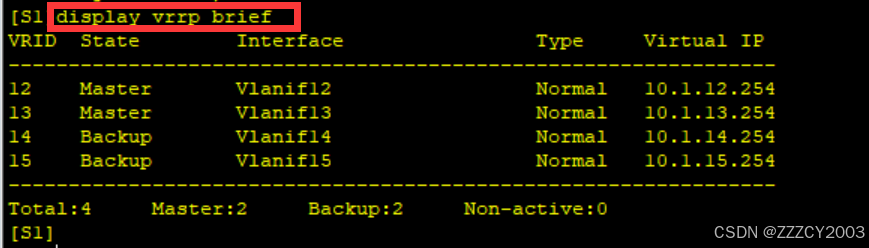
验证
(5)配置NAT
配置NAT使得总部和分公司的主机可以通过路由器SZ访问Internet
SZ配置
展开代码[SZ]acl number 2000
[SZ-acl-basic-2000]rule 10 permit source 192.168.2.0 0.0.1.255
[SZ-acl-basic-2000]rule 20 permit source 172.16.8.0 0.0.3.255
[SZ-acl-basic-2000]rule 30 permit source 10.1.12.0 0.0.3.255
[SZ-acl-basic-2000]quit
[SZ]interface GigabitEthernet4/0/0
[SZ-GigabitEthernet4/0/0]nat outbound 2000
[SZ-GigabitEthernet4/0/0]quit
项目核心(OSPF)
(1)配置OSPF基本功能
配置OSPF时,可以将拓扑图简化为
3台路由器和4台交换机配置基本OSPF,包括创建OSPF进程,手动指定Router ID、修改度量值计算的参考带宽、激活运行OSPF的路由器接口以及配置静默接口等
SZ配置
展开代码[SZ]ospf 1 router-id 1.1.1.1
[SZ-ospf-1]bandwidth-reference 1000
[SZ-ospf-1]area 0
[SZ-ospf-1-area-0.0.0.0]network 10.2.2.1 0.0.0.0
[SZ-ospf-1-area-0.0.0.0]network 10.2.3.1 0.0.0.0
[SZ-ospf-1]area 1
[SZ-ospf-1-area-0.0.0.1]network 172.16.12.2 0.0.0.0
[SZ-ospf-1]area 2
[SZ-ospf-1-area-0.0.0.2]network 192.168.12.1 0.0.0.0
GZ配置
展开代码[GZ]ospf 1 router-id 2.2.2.2
[GZ-ospf-1]bandwidth-reference 1000
[GZ-ospf-1]area 1
[GZ-ospf-1-area-0.0.0.1]network 172.16.6.2 0.0.0.0
[GZ-ospf-1-area-0.0.0.1]network 172.16.12.1 0.0.0.0
BJ配置
展开代码[BJ]ospf 1 router-id 3.3.3.3
[BJ-ospf-1]bandwidth-reference 1000
[BJ-ospf-1]area 2
[BJ-ospf-1-area-0.0.0.2]network 192.168.6.1 0.0.0.0
[BJ-ospf-1-area-0.0.0.2]network 192.168.12.2 0.0.0.0
S1配置
展开代码[S1]ospf 1 router-id 4.4.4.4
[S1-ospf-1]bandwidth-reference 1000
[S1-ospf-1]area 0
[S1-ospf-1-area-0.0.0.0]network 10.2.2.2 0.0.0.0
[S1-ospf-1-area-0.0.0.0]network 10.1.12.252 0.0.0.0
[S1-ospf-1-area-0.0.0.0]network 10.1.13.252 0.0.0.0
[S1-ospf-1-area-0.0.0.0]network 10.1.14.252 0.0.0.0
[S1-ospf-1-area-0.0.0.0]network 10.1.15.252 0.0.0.0
S2配置
展开代码[S2]ospf 1 router-id 5.5.5.5
[S2-ospf-1]bandwidth-reference 1000
[S2-ospf-1]area 0
[S2-ospf-1-area-0.0.0.0]network 10.2.3.2 0.0.0.0
[S2-ospf-1-area-0.0.0.0]network 10.1.12.253 0.0.0.0
[S2-ospf-1-area-0.0.0.0]network 10.1.13.253 0.0.0.0
[S2-ospf-1-area-0.0.0.0]network 10.1.14.253 0.0.0.0
[S2-ospf-1-area-0.0.0.0]network 10.1.15.253 0.0.0.0
S5配置
展开代码[S5]ospf 1 router-id 6.6.6.6
[S5-ospf-1]silent-interface Vlanif22
[S5-ospf-1]silent-interface Vlanif33
[S5-ospf-1]silent-interface Vlanif44
[S5-ospf-1]silent-interface Vlanif55
[S5-ospf-1]bandwidth-reference 1000
[S5-ospf-1]area 1
[S5-ospf-1-area-0.0.0.1]network 172.16.6.1 0.0.0.0
[S5-ospf-1-area-0.0.0.1]network 172.16.8.254 0.0.0.0
[S5-ospf-1-area-0.0.0.1]network 172.16.9.254 0.0.0.0
[S5-ospf-1-area-0.0.0.1]network 172.16.10.254 0.0.0.0
[S5-ospf-1-area-0.0.0.1]network 172.16.11.254 0.0.0.0
S6配置
展开代码[S6]ospf 1 router-id 7.7.7.7
[S6-ospf-1]silent-interface Vlanif222
[S6-ospf-1]silent-interface Vlanif333
[S6-ospf-1]bandwidth-reference 1000
[S6-ospf-1]area 2
[S6-ospf-1-area-0.0.0.2]network 192.168.6.2 0.0.0.0
[S6-ospf-1-area-0.0.0.2]network 192.168.2.254 0.0.0.0
[S6-ospf-1-area-0.0.0.2]network 192.168.3.254 0.0.0.0
(2)配置OSPF Stub区域
配置OSPF 特殊区域,将区域2配置为完全末节区域
SZ配置
展开代码[SZ-ospf-1]area 2
[SZ-ospf-1-area-0.0.0.2]stub no-summary
BJ配置
展开代码[BJ-ospf-1]area2
[BJ-ospf-1-area-0.0.0.2]stub
S6配置
展开代码[S6-ospf-1]area 2
[S6-ospf-1-area-0.0.0.2]stub
(3)配置OSPF验证
在深圳总部到广州分公司和北京分公司的两条链路上配置OSPF的MD5验证
展开代码[SZ]interface GigabitEthernet 0/0/0
[SZ-GigabitEthernet0/0/0]ospf authentication-mode md5 1 cipher 123456
[SZ-GigabitEthernet0/0/0]quit

[SZ]interface GigabitEthernet 0/0/1
[SZ-GigabitEthernet0/0/1]ospf authentication-mode md5 1 cipher 123456
[SZ-GigabitEthernet0/0/1]quit

[GZ]interface GigabitEthernet 0/0/0
[GZ-GigabitEthernet0/0/0]ospf authentication-mode md5 1 cipher 123456
[GZ-GigabitEthernet0/0/0]quit

[BJ]interface GigabitEthernet 0/0/1
[BJ-GigabitEthernet0/0/1]ospf authentication-mode md5 1 cipher 123456
[BJ-GigabitEthernet0/0/1]quit
在深圳总部的设备SZ、S1、S2上配置OSPF Area 0的MD5验证
展开代码# 配置OSPF Area0 的MD5验证
[SZ]ospf 1
[SZ-ospf-1]area 0
[SZ-ospf-1-area-0.0.0.0]authentication-mode md5 1 cipher 123456

[S1]ospf 1
[S1-ospf-1]area 0
[S1-ospf-1-area-0.0.0.0]authentication-mode md5 1 cipher 123456

[S2]ospf 1
[S2-ospf-1]area 0
[S2-ospf-1-area-0.0.0.0]authentication-mode md5 1 cipher 123456
(4)配置OSPF路由聚合
在路由器SZ上分别配置OSPF区域0、1和2的ABR路由聚合,以便减少路由表大小,提高路由查找效率
SZ配置
展开代码[SZ-ospf-1]area 0
[SZ-ospf-1-area-0.0.0.0]abr-summary 10.1.12.0 255.255.252.0
[SZ-ospf-1]area 1
[SZ-ospf-1-area-0.0.0.1]abr-summary 172.16.8.0 255.255.252.0
[SZ-ospf-1]area 2
[SZ-ospf-1-area-0.0.0.2]abr-summary 192.168.2.0 255.255.254.0
(5)配置OSPF默认路由注入
在路由器SZ上配置指向ISP的静态默认路由,并向OSPF网络注入默认路由
SZ配置
展开代码[SZ]ip route-static 0.0.0.0 0.0.0.0 218.18.12.2
[SZ]ospf 1
[SZ-ospf-1]default-route-advertise
(6)控制OSPF DR选举
控制OSPF DR选举,使得路由器SZ成为连接三层交换机S1和S2的相应网段的DR
SZ配置
展开代码[SZ]interface GigabitEthernet0/0/2
[SZ-GigabitEthernet0/0/2]ospf dr-priority 2
[SZ]interface GigabitEthernet1/0/0
[SZ-GigabitEthernet1/0/0]ospf dr-priority 2
(7)调控OSPF计时器
调整OSPF接口计时器参数,在路由器SZ和BJ之间链路上调整OSPF计时器参数
SZ配置
展开代码[SZ]interface GigabitEthernet0/0/1
[SZ-GigabitEthernet0/0/1]ospf timer hello 5
[SZ-GigabitEthernet0/0/1]ospf timer dead 20
BJ配置
展开代码[BJ]interface GigabitEthernet0/0/1
[BJ-GigabitEthernet0/0/1]ospf timer hello 5
[BJ-GigabitEthernet0/0/1]ospf timer dead 20
基本上就是这样,至于剩下的查看LSDB等信息,就不在这里进行查询了(可以下载实验包,自己搞)
实验包
本文作者:zzz
本文链接:
版权声明:本博客所有文章除特别声明外,均采用 BY-NC-SA 许可协议。转载请注明出处!